路由交换-作业5-配置DTP
路由交换-作业5-配置DTP
当前进度 1.00
更新地址:
博客正在准备装修,临时可能打开速度有点慢
更新中修改的内容
在试错过程中发现并修改的内容:
目前没有
0x00 准备
如果遇到无法登录的问题,下载新版的软件,在登录服务器选择的时候选择:Ch_na
文件下载:
https://p.dabbit.net/blog/pic_bed/2023/03/04ef5b53261668b5_202303232015005.zip
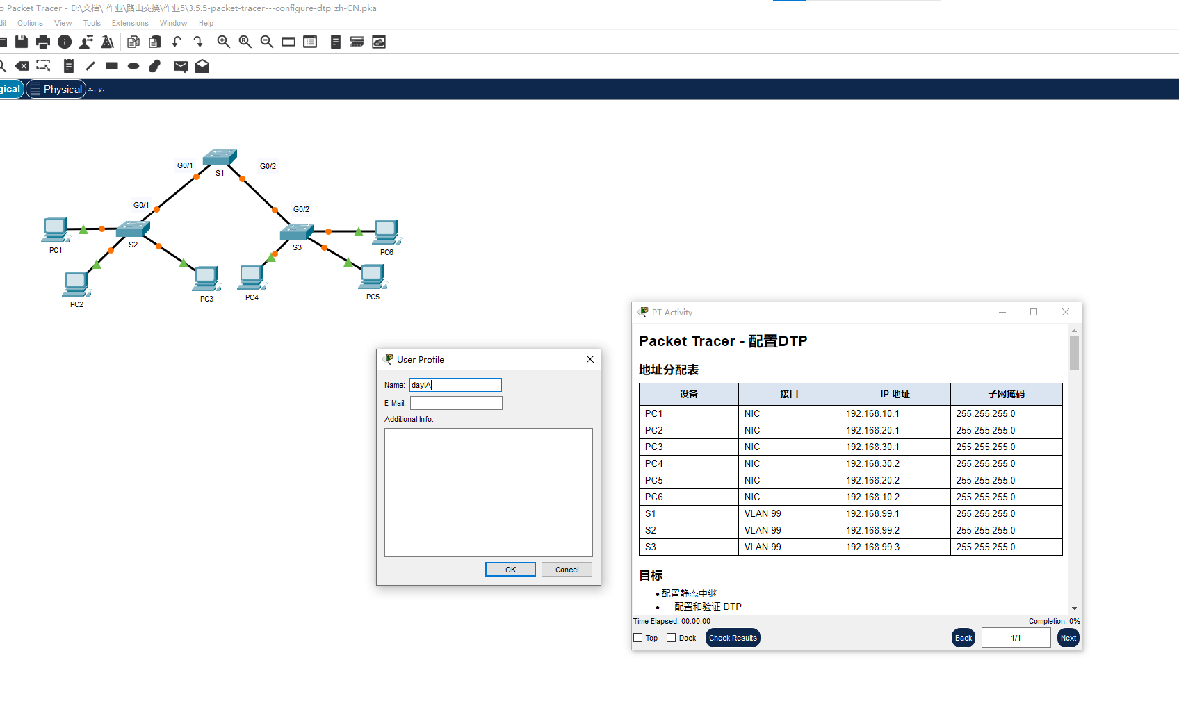
看上去不是很多的样子诶
0x01 题目描述
地址分配表
| 设备 | 接口 | IP 地址 | 子网掩码 |
|---|---|---|---|
| PC1 | NIC | 192.168.10.1 | 255.255.255.0 |
| PC2 | NIC | 192.168.20.1 | 255.255.255.0 |
| PC3 | NIC | 192.168.30.1 | 255.255.255.0 |
| PC4 | NIC | 192.168.30.2 | 255.255.255.0 |
| PC5 | NIC | 192.168.20.2 | 255.255.255.0 |
| PC6 | NIC | 192.168.10.2 | 255.255.255.0 |
| S1 | VLAN 99 | 192.168.99.1 | 255.255.255.0 |
| S2 | VLAN 99 | 192.168.99.2 | 255.255.255.0 |
| S3 | VLAN 99 | 192.168.99.3 | 255.255.255.0 |
目标
. 配置静态中继
. 配置并验证 DTP
背景**/**场景
随着网络中的交换机数量增加,管理 VLAN 和中继所需执行的管理工作可能越来越具有挑战性。为了简化一些 VLAN 和中继的配置, 网络设备之间的中继协商由动态中继协议 (DTP) 进行管理,并在 Catalyst 2960 和 Catalyst 3560 交换机上自动启用。
在此练习中,您将配置交换机之间的中继链路。您需要把端口划分到 VLAN 当中, 然后验证同一个 VLAN 当中 各个主机之间的连通性。您需要配置交换机之间的干道链路,并且把 VLAN 999 配置为本征 VLAN。
0x10 指导
验证交换机上配置的 VLAN。
0x10ab 指导.ab
a. 在 S1 上,进入特权 EXEC 模式,并且输入show vlan brief 命令来验证当前的一些 VLAN。
打开配置窗口
S1# show vlan brief#输出 VLAN Name Status Ports ---- -------------------------------- --------- ------------------------------- 1 default active Fa0/1, Fa0/2, Fa0/3, Fa0/4 Fa0/5, Fa0/6, Fa0/7,Fa0/8 Fa0/9, Fa0/10, Fa0/11, Fa0/12 Fa0/13, Fa0/14, Fa0/15,Fa0/16 Fa0/17, Fa0/18, Fa0/19,Fa0/20 Fa0/21, Fa0/22, Fa0/23,Fa0/24 Gig0/1, Gig0/2 99 Management active 999 Native active 1002 fddi-default active 1003 token-ring-default active 1004 fddinet-default active 1005 trnet-default activeb. 在 S2 和 S3 上重复步骤 1a。
S1交换机:
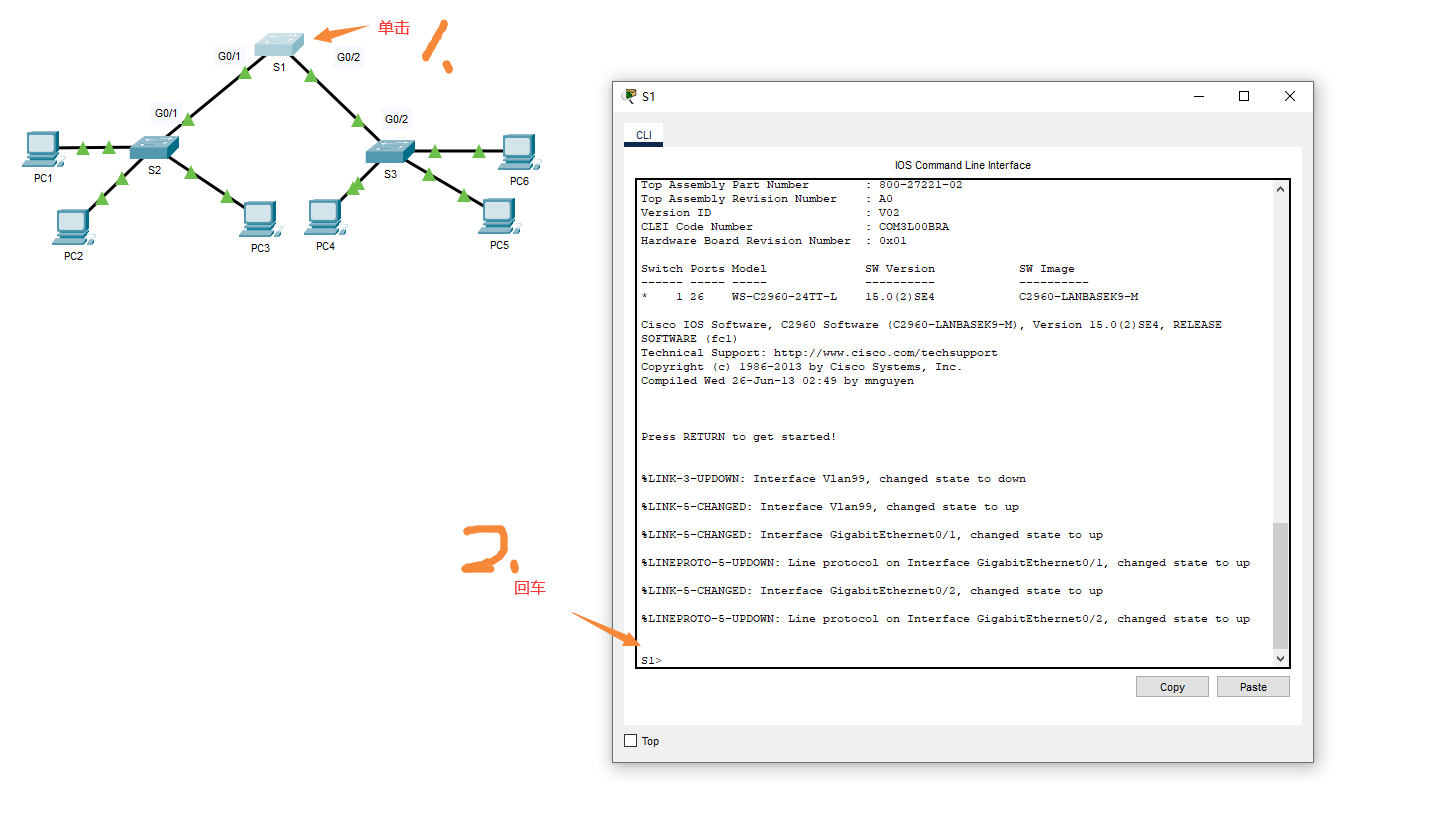
执行:
S1>enable
S1#show vlan brief
三个交换机都这样执行:
S2>enable
S2#show vlan brief

S3>enable
S3#show vlan brief

[Tab可以补全命令]
sh[按下tab] =show
show vl[按下tab] = show vlan
show vlan bri[按下tab] = show vlan brief
输出内容:
S1#show vlan brief

VLAN Name                             Status    Ports
---- -------------------------------- --------- -------------------------------
1    default                          active    Fa0/1, Fa0/2, Fa0/3, Fa0/4
                                                Fa0/5, Fa0/6, Fa0/7, Fa0/8
                                                Fa0/9, Fa0/10, Fa0/11, Fa0/12
                                                Fa0/13, Fa0/14, Fa0/15, Fa0/16
                                                Fa0/17, Fa0/18, Fa0/19, Fa0/20
                                                Fa0/21, Fa0/22, Fa0/23, Fa0/24
                                                Gig0/1, Gig0/2
99   Management                       active
999  Native                           active
1002 fddi-default                     active
1003 token-ring-default               active
1004 fddinet-default                  active
1005 trnet-default                    active


S2>enable
S2#show vlan brief

VLAN Name                             Status    Ports
---- -------------------------------- --------- -------------------------------
1    default                          active    Fa0/1, Fa0/2, Fa0/3, Fa0/4
                                                Fa0/5, Fa0/6, Fa0/7, Fa0/8
                                                Fa0/9, Fa0/10, Fa0/11, Fa0/12
                                                Fa0/13, Fa0/14, Fa0/15, Fa0/16
                                                Fa0/17, Fa0/18, Fa0/19, Fa0/20
                                                Fa0/21, Fa0/22, Fa0/23, Fa0/24
                                                Gig0/1, Gig0/2
99   Management                       active
999  Native                           active
1002 fddi-default                     active
1003 token-ring-default               active
1004 fddinet-default                  active
1005 trnet-default                    active


S3>enable
S3#show vlan brief
VLAN Name                             Status    Ports
---- -------------------------------- --------- -------------------------------
1    default                          active    Fa0/1, Fa0/2, Fa0/3, Fa0/4
                                                Fa0/5, Fa0/6, Fa0/7, Fa0/8
                                                Fa0/9, Fa0/10, Fa0/11, Fa0/12
                                                Fa0/13, Fa0/14, Fa0/15, Fa0/16
                                                Fa0/17, Fa0/18, Fa0/19, Fa0/20
                                                Fa0/21, Fa0/22, Fa0/23, Fa0/24
                                                Gig0/1, Gig0/2
99   Management                       active
999  Native                           active
1002 fddi-default                     active
1003 token-ring-default               active
1004 fddinet-default                  active
1005 trnet-default                    active
Q.0x10.b 交换机上配置了哪些 VLAN?
该交换机上配置了以下 VLAN:
- VLAN 1(默认 VLAN):所有端口都在此 VLAN 中,且该 VLAN 处于激活状态。
- VLAN 99:名称为 Management 的 VLAN,处于激活状态。
- VLAN 999:Native VLAN,处于激活状态。
- VLAN 1002:fddi-default VLAN,处于激活状态。
- VLAN 1003:token-ring-default VLAN,处于激活状态。
- VLAN 1004:fddinet-default VLAN,处于激活状态。
- VLAN 1005:trnet-default VLAN,处于激活状态。
0x20 第 2 部分: 在 S2 和 S3 上创建其他 VLAN。
0x20abc
a. 在 S2 上, 创建 VLAN 10,并且把它命名为 Red。
S2(config)# vlan 10
S2(config-vlan)# name Red
b. 根据下表创建 VLAN 20 和 30。
VLAN 编号 VLAN 名称 10 Red 20 Blue 30 Yellow c. 验证新添加的 VLAN 。在特权 EXEC 模式下输入 show vlan brief。
在S2上输入以下命令:
S2>enable
S2#conf t

#a部分
S2(config)#vlan 10
S2(config-vlan)#name Red

#b部分
#这里可以直接输入vlan 20  从config-vlan 切换到config-vlan
S2(config-vlan)#vlan 20
S2(config-vlan)#name Blue

S2(config-vlan)#vlan 30
S2(config-vlan)#name Yellow

#c部分
S2(config-vlan)#end
S2#show vlan  brief
c部分输出:
VLAN Name                             Status    Ports
---- -------------------------------- --------- -------------------------------
1    default                          active    Fa0/1, Fa0/2, Fa0/3, Fa0/4
                                                Fa0/5, Fa0/6, Fa0/7, Fa0/8
                                                Fa0/9, Fa0/10, Fa0/11, Fa0/12
                                                Fa0/13, Fa0/14, Fa0/15, Fa0/16
                                                Fa0/17, Fa0/18, Fa0/19, Fa0/20
                                                Fa0/21, Fa0/22, Fa0/23, Fa0/24
                                                Gig0/1, Gig0/2
10   Red                              active
20   Blue                             active
30   Yellow                           active
99   Management                       active
999  Native                           active
1002 fddi-default                     active
1003 token-ring-default               active
1004 fddinet-default                  active
1005 trnet-default                    active
Q.0x20c 除了默认 VLAN 之外, S2 上还配置了哪些 VLAN?
VLAN 10   Red
VLAN 20   Blue
VLAN 30   Yellow
VLAN 99   Management
VLAN 999  Native
0x20d
d. 在 S3 上重复前面的步骤,创建其他 VLAN。
在S3上重复上面的步骤
S3>enable
S3#conf t
	[Enter configuration commands, one per line.  End with CNTL/Z.]
S3(config)#vlan 10
S3(config-vlan)#name Red

S3(config-vlan)#vlan 20
S3(config-vlan)#name Blue

S3(config-vlan)#vlan 30
S3(config-vlan)#name Yellow

S3(config-vlan)#end
S3#
0x30 第 3 部分:为端口分配 VLAN
使用 switchport mode access 命令对每条接入链路设置接入模式。使用 switchport access vlan vlan-id 命 令把一个 VLAN 分配给一个接入端口。
端口 分配 网络 S2 F0/1 – 8 S3 F0/1 – 8 VLAN 10 (Red) 192.168.10.0 /24 S2 F0/9 – 16 S3 F0/9 – 16 VLAN 20 (Blue) 192.168.20.0 /24 S2 F0/17 – 24 S3 F0/17 – 24 VLAN 30 (Yellow) 192.168.30.0 /24
0x30a 第三部分.a
a. 使用上表中的分配,将 VLAN 分配给 S2 上的端口。
S2(config-if)# interface range f0/1 - 8
S2(config-if-range)# switchport mode access
S2(config-if-range)# switchport access vlan 10
S2(config-if-range)# interface range f0/9 -16
S2(config-if-range)# switchport mode access
S2(config-if-range)# switchport access vlan 20
S2(config-if-range)# interface range f0/17 - 24
S2(config-if-range)# switchport mode access
S2(config-if-range)# switchport access vlan 30
在S2交换机上,执行这些语句就可以啦:
#步骤a
S2#conf t
	[Enter configuration commands, one per line.  End with CNTL/Z.]
S2(config)#

S2(config-if)# interface range f0/1 - 8
S2(config-if-range)# switchport mode access
S2(config-if-range)# switchport access vlan 10
S2(config-if-range)# interface range f0/9 - 16
S2(config-if-range)# switchport mode access
S2(config-if-range)# switchport access vlan 20
S2(config-if-range)# interface range f0/17 - 24
S2(config-if-range)# switchport mode access
S2(config-if-range)# switchport access vlan 30
0x30b 第三部分.b
b. 按照上表的分配方式, 把 S3 上面的端口划分到 VLAN 当中。
在把端口划分到 VLAN 中之后,尝试从 PC1 向 PC6 执行 ping 操作。
在S3交换机上执行一样的命令:
#步骤b

S3#conf t
	[Enter configuration commands, one per line.  End with CNTL/Z.]
S3(config)# interface range f0/1 - 8
S3(config-if-range)#switchport mode access
S3(config-if-range)#switchport access vlan 10
S3(config-if-range)#interface range f0/9 - 16
S3(config-if-range)#switchport mode access
S3(config-if-range)#switchport access vlan 20
S3(config-if-range)#interface range f0/17 - 24
S3(config-if-range)#switchport mode access
S3(config-if-range)#switchport access vlan 30
S3(config-if-range)#end
尝试ping
这里的PC1-6好像都已经配好IP啦,只需要执行就可以啦。
-
PC-1 : 192.168.10.1
-
PC-6 : 192.168.10.2
PC1 CMD执行:
ping 192.168.10.2
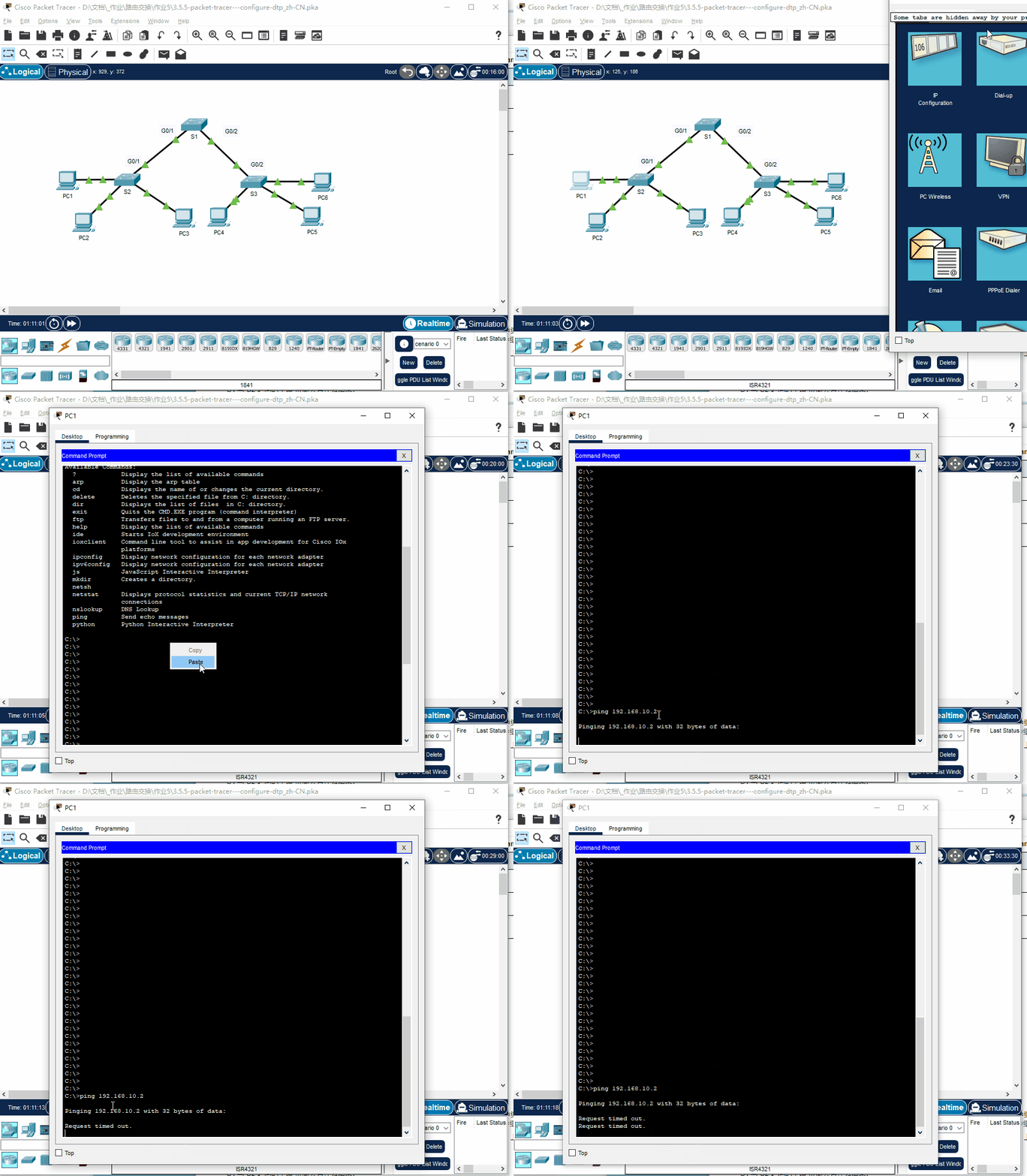
Q.0x30b ping 操作是否成功?说明原因。
失败,因为
- 交换机之间的端口在 VLAN 1
- PC1、PC6 的端口在VLAN 10
要让它们相互通信,需要进行跨 VLAN 通信。
0x40 第 4 部分: 在 S1 、S2 和 S3 上配置中继。
动态中继协议 (DTP) 管理思科交换机之间的中继链路。目前,所有交换机端口都处于默认中继协商模式, 即 “dynamic auto (动态自动) ”模式。在此步骤中,您将为交换机 S1 与 S2 之间的链路将中继协商模式改为“动态 期望”模式。交换机 S1 与 S3 之间的链路需要为静态中继模式。在此拓扑中, 使用 VLAN 999 作为本征 VLAN。
0x40a 第4部分.a
在交换机 S1 上, 在接口 GigabitEthernet 0/1 上把中继协商模式配置为 dynamic desirable 。S1 的配置如下 所示。
S1(config)# interface g0/1
S1(config-if)# switchport mode dynamic desirable
S1>enable
S1#conf t
	[Enter configuration commands, one per line.  End with CNTL/Z.]
S1(config)#interface g0/1
S1(config-if)#switchport mode dynamic desirable

S1(config-if)#
	[%LINEPROTO-5-UPDOWN: Line protocol on Interface GigabitEthernet0/1, changed state to up]

	[%LINEPROTO-5-UPDOWN: Line protocol on Interface GigabitEthernet0/1, changed state to down]

	[%LINEPROTO-5-UPDOWN: Line protocol on Interface GigabitEthernet0/1, changed state to up]

	[%LINEPROTO-5-UPDOWN: Line protocol on Interface Vlan99, changed state to up]

S1(config-if)#end
S1#
Q.0x40a S1 与 S2 之间中继协商的结果是什么?
交换机 S1 和 S2 之间,
-
S1 接口 GigabitEthernet 0/1 的中继协商模式被配置为 dynamic desirable
-
S2 接口 GigabitEthernet 0/1 的中继协商模式默认为 dynamic auto
-
S2 接口 GigabitEthernet 0/1 会自动变为动态可接受模式 dynamic desirable
-
S1 和 S2 之间的链路将使用动态中继协议 (DTP) 进行中继。
S1 与 S2 建立了中继链路
0x40b 第4部分.b
b. 在交换机 S2 上, 输入 show interfaces trunk 命令验证中继是否已经协商。 GigabitEthernet 0/1 接口应出 现在输出信息当中。
S2>enable
S2#show interfaces trunk
Port        Mode         Encapsulation  Status        Native vlan
Gig0/1      auto         n-802.1q       trunking      1

Port        Vlans allowed on trunk
Gig0/1      1-1005

Port        Vlans allowed and active in management domain
Gig0/1      1,10,20,30,99,999

Port        Vlans in spanning tree forwarding state and not pruned
Gig0/1      1,10,20,30,99,999

S2#
Q.0x40b 这个端口的模式和状态是什么
- 模式为:auto
- 状态为:turunking
已经建立连接
S2 的 GigabitEthernet 0/1 接口处于 trunking
支持的 VLAN ID 为 1-1005
激活的 VLAN ID 包括 1,10,20,30,99,999。
S1 和 S2 之间已经成功协商为 trunk 模式,允许传送的 VLAN 包括了本拓扑中所有的 VLAN。
0x40cde 第4部分.cde
c. 对于 S1 和 S3 之间的中继链路,需要在 S1 上把接口 GigabitEthernet 0/2 配置为静态中继。此外,需要在 S1 的 G0/2 接口上禁用 DTP 协商。
S1(config)# interface g0/2
S1(config-if)# switchport mode trunk
S1(config-if)# switchport nonegotiate
d. 使用 show dtp 命令验证 DTP 的状态
S1# show dtp
Global DTP information
Sending DTP Hello packets every 30 seconds
Dynamic Trunk timeout is 300 seconds
1 interfaces using DTP
e. 使用 show interfaces trunk 命令验证所有交换机是否均已启用中继。
S1# show interfaces trunk
Port Mode Encapsulation Status Native vlan
Gig0/1 desirable n-802.1q trunking 1
Gig0/2 on 802.1q trunking 1

Port Vlans allowed on trunk
Gig0/1 1-1005
Gig0/2 1-1005

Port Vlans allowed and active in management domain
Gig0/1 1,99,999
Gig0/2 1,99,999

Port Vlans in spanning tree forwarding state and not pruned
Gig0/1 1,99,999
Gig0/2 1,99,999
#c 对于 S1 和 S3 之间的中继链路,需要在 S1 上把接口 GigabitEthernet 0/2 配置为静态中继。此外,需要在 S1 的 G0/2 接口上禁用 DTP 协商。

S1>enable
S1#conf t
	[Enter configuration commands, one per line.  End with CNTL/Z.]
S1(config)#interface g0/2
S1(config-if)#switchport mode trunk
S1(config-if)#switchport nonegotiate

S1(config-if)#end

#d  使用 **show** **dtp** 命令验证 DTP 的状态
S1#show dtp
Global DTP information
    Sending DTP Hello packets every 30 seconds
    Dynamic Trunk timeout is 300 seconds
    1 interfaces using DTP


#e 使用 **show** **interfaces** **trunk** 命令验证所有交换机是否均已启用中继。
S1#show interfaces trunk
Port        Mode         Encapsulation  Status        Native vlan
Gig0/1      desirable    n-802.1q       trunking      1
Gig0/2      on           802.1q         trunking      1

Port        Vlans allowed on trunk
Gig0/1      1-1005
Gig0/2      1-1005

Port        Vlans allowed and active in management domain
Gig0/1      1,99,999
Gig0/2      1,99,999

Port        Vlans in spanning tree forwarding state and not pruned
Gig0/1      1,99,999
Gig0/2      1,99,999
来自ciscoPDF:
switchport nonegotiate: 严格的说,这不算是种接口模式,它的作用只 是阻止交换机接口发出DTP 数据包,它必须与switchport mode trunk 或者 switchport mode access 一起使用。
来自cisco社区:
当链路的一端设置为配置为trunk加nonegotiate(switchport mode trunk 加switchport nonegotiate ),另外一端设置为dynamic auto或者dynamic desirable时,配置为trunk的一端成为TRUNK模式,而另外一端最终处于Access模式(因为协商失败)。这是一种错误的配置方法。 switchport nonegotiate命令不能单独使用,一定与switchport mode trunk命令配合使用。两者合起来的含义为:本端口工作模式一定是TRUNK并且不协商。因此一端如此配置后,要求对端必须也配置成trunk模式(switchport mode trunk)。
来自cdsn:
DTP • 它的前身是DISL — Dynamic ISL • 它们都是思科私有的协议,用于协商Trunk链路(类型为0X2004的组播 MAC:01-00-0C-CC-CC-CC,每间隔一秒发送一次,形成干道之后间隔30秒发送) • Trunk – ON 默认发送DTP( switchport mode trunk ) – OFF 用命令“ switchport nonegotiate ”关掉DTP • Dynamic – Auto 默认不发送DTP,但是收到DTP后可以回复,被动协商[switchport mode dynamic auto] – Desirable 默认主动发送DTP,主动协商[switchport mode dynamic desirable] • Access 不发送DTP,不协商Trunk
Sw1(config-if)#switchport mode dynamic desirable(默认模式) Sw1(config-if)#switchport mode dynamic auto (被动模式) Sw1(config-if)#switchport nonegotiate (nonegotiate只能和trunk联用)
原文链接:https://blog.csdn.net/qq_40170955/article/details/107552478
Q.0x40e 目前这些中继的本征 VLAN 是什么?
本征VLAN 也叫 Native VLAN,是在一个 802.1Q 标记帧中没有被打上 VLAN 标记的默认 VLAN。
交换机之间进行 VLAN 中继时,如果两端的本征 VLAN 不同,可能会出现一些安全问题。
在中继链路上设置尽可能相同的本征 VLAN。
Q.0x40e 答案:
- S1 与 S2 之间的中继本征 VLAN 为 VLAN 1。
- S1 与 S3 之间的中继本征 VLAN 为 VLAN 1。
这些中继的本征 VLAN 都为 VLAN 1
0x40f 第4部分.f
f. 将 VLAN 999 配置为 S1 上的中继链路的本征 VLAN。
S1(config)# interface range g0/1-2
S1(config-if-range)# switchport trunk native vlan 999
switchport nonegotiate 命令用于禁止交换机接口之间的动态协议交换(DTP)。当两个接口都配置为 trunk 模式时,默认情况下它们会通过 DTP 协商确认是否需要建立一个 trunk 连接。使用 switchport nonegotiate 命令可以禁用 DTP 协商,从而强制接口成为 trunk 连接
S1#conf t
Enter configuration commands, one per line.  End with CNTL/Z.
S1(config)#interface range g0/1-2
S1(config-if-range)#switchport trunk native vlan 999

信息:
%SPANTREE-2-RECV_PVID_ERR: Received BPDU with inconsistent peer vlan id 1 on GigabitEthernet0/1 VLAN999.

%SPANTREE-2-BLOCK_PVID_LOCAL: Blocking GigabitEthernet0/1 on VLAN0999. Inconsistent local vlan.

%CDP-4-NATIVE_VLAN_MISMATCH: Native VLAN mismatch discovered on GigabitEthernet0/1 (999), with S2 GigabitEthernet0/1 (1).
Q. 0x40f 您在 S1 上收到什么消息?您将如何纠正?
信息:
%SPANTREE-2-RECV_PVID_ERR: Received BPDU with inconsistent peer vlan id 1 on GigabitEthernet0/1 VLAN999.

%SPANTREE-2-BLOCK_PVID_LOCAL: Blocking GigabitEthernet0/1 on VLAN0999. Inconsistent local vlan.

%CDP-4-NATIVE_VLAN_MISMATCH: Native VLAN mismatch discovered on GigabitEthernet0/1 (999), with S2 GigabitEthernet0/1 (1).
本征(native) VLAN 不匹配,需要在S2 S3上将VLAN999 配置为默认的VLAN。
0x40.ghi
g. 在 S2 和 S3 上,将 VLAN 999 配置为本征 VLAN。
S2执行:
S2>enable
S2#conf t
	[Enter configuration commands, one per line.  End with CNTL/Z.]

S2(config)#interface g0/1

	可能弹出的报错,正常:[%CDP-4-NATIVE_VLAN_MISMATCH: Native VLAN mismatch discovered on GigabitEthernet0/1 (1), with S1 GigabitEthernet0/1 (999).]

S2(config-if)#switchport mode trunk
S2(config-if)#switchport trunk native vlan 999
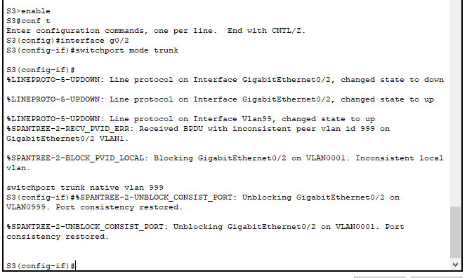
S3执行:
S3>enable
S3#conf t
S3(config)#interface g0/2
S3(config-if)#switchport mode trunk
S3(config-if)#switchport trunk native vlan 999
S3(config-if)#end
输入的过程可能会弹出报错,正常现象。
0x40.h 第4部分.h
h. 验证是否已在所有交换机上成功配置中继。您应该能够使用 SVI 上配置的 IP 地址从拓扑中的其他交换机对 一台交换机执行 ping 操作。
别忘了这个:
| 设备 | 接口 | IP 地址 |
|---|---|---|
| S1 | VLAN 99 | 192.168.99.1 |
| S2 | VLAN 99 | 192.168.99.2 |
| S23 | VLAN 99 | 192.168.99.3 |
在S1上执行:
#
S1>ping 192.168.99.3

Type escape sequence to abort.
Sending 5, 100-byte ICMP Echos to 192.168.99.3, timeout is 2 seconds:
..!!!
Success rate is 60 percent (3/5), round-trip min/avg/max = 0/0/0 ms


S1>ping 192.168.99.2

Type escape sequence to abort.
Sending 5, 100-byte ICMP Echos to 192.168.99.2, timeout is 2 seconds:
..!!!
Success rate is 60 percent (3/5), round-trip min/avg/max = 0/0/0 ms
0x40.i 第4部分.i
i. 尝试从 PC1 Ping PC6。
在PC1上的CMD里面:
失败了:
C:\>ping 192.168.10.2

Pinging 192.168.10.2 with 32 bytes of data:

Request timed out.
Q.0x40.i Ping 是否不成功?(提示: 在这 3 台交换机上查看命令‘show vlan brief’的输出信息。与所有交换机上使 用‘show interface trunk’命令的输出信息进行比较)
show vlan brief

S1#show vlan brief

VLAN Name                             Status    Ports
---- -------------------------------- --------- -------------------------------
1    default                          active    Fa0/1, Fa0/2, Fa0/3, Fa0/4
                                                Fa0/5, Fa0/6, Fa0/7, Fa0/8
                                                Fa0/9, Fa0/10, Fa0/11, Fa0/12
                                                Fa0/13, Fa0/14, Fa0/15, Fa0/16
                                                Fa0/17, Fa0/18, Fa0/19, Fa0/20
                                                Fa0/21, Fa0/22, Fa0/23, Fa0/24
99   Management                       active
999  Native                           active
1002 fddi-default                     active
1003 token-ring-default               active
1004 fddinet-default                  active
1005 trnet-default                    active


S2# show vlan brief

VLAN Name                             Status    Ports
---- -------------------------------- --------- -------------------------------
1    default                          active    Gig0/2
10   Red                              active    Fa0/1, Fa0/2, Fa0/3, Fa0/4
                                                Fa0/5, Fa0/6, Fa0/7, Fa0/8
20   Blue                             active    Fa0/9, Fa0/10, Fa0/11, Fa0/12
                                                Fa0/13, Fa0/14, Fa0/15, Fa0/16
30   Yellow                           active    Fa0/17, Fa0/18, Fa0/19, Fa0/20
                                                Fa0/21, Fa0/22, Fa0/23, Fa0/24
99   Management                       active
999  Native                           active
1002 fddi-default                     active
1003 token-ring-default               active
1004 fddinet-default                  active
1005 trnet-default                    active


S3#show vlan brief

VLAN Name                             Status    Ports
---- -------------------------------- --------- -------------------------------
1    default                          active    Gig0/1
10   Red                              active    Fa0/1, Fa0/2, Fa0/3, Fa0/4
                                                Fa0/5, Fa0/6, Fa0/7, Fa0/8
20   Blue                             active    Fa0/9, Fa0/10, Fa0/11, Fa0/12
                                                Fa0/13, Fa0/14, Fa0/15, Fa0/16
30   Yellow                           active    Fa0/17, Fa0/18, Fa0/19, Fa0/20
                                                Fa0/21, Fa0/22, Fa0/23, Fa0/24
99   Management                       active
999  Native                           active
1002 fddi-default                     active
1003 token-ring-default               active
1004 fddinet-default                  active
1005 trnet-default                    active
发现S1 的VLAN设置不正确。
0x40.j 第4部分.j
j. 如果需要,对配置进行更正。
在S1上执行:
S1#conf t
S1(config)#vlan 10
S1(config-vlan)#name Red
S1(config-vlan)#vlan 20
S1(config-vlan)#name Blue
S1(config-vlan)#vlan 30
S1(config-vlan)#name Yellow
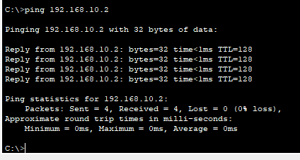
再次测试
ping 192.168.10.2
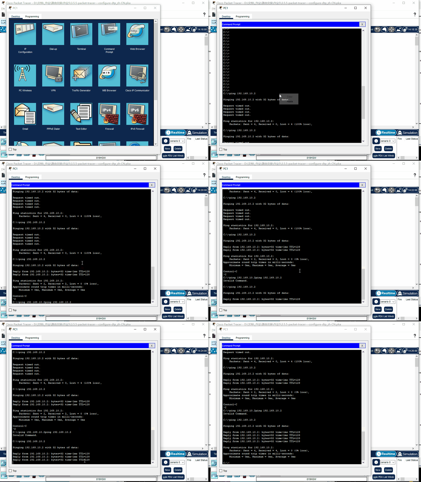
通啦:
0x50 第 5 部分: 重新在 S3 上配置干道。
a. 在 S3 上输入‘show interface trunk’命令。
S3#show interface trunk
Port        Mode         Encapsulation  Status        Native vlan
Gig0/2      on           802.1q         trunking      999

Port        Vlans allowed on trunk
Gig0/2      1-1005

Port        Vlans allowed and active in management domain
Gig0/2      1,10,20,30,99,999

Port        Vlans in spanning tree forwarding state and not pruned
Gig0/2      1,10,20,30,99,999
Q.0x50.a G0/2 上的模式和封装是什么?
-
接口Gig0/2 模式:on
-
此端口配置为静态访问或静态特定于 VLAN 的接口。
-
接口Gig0/2 封装:802.1q
-
使用IEEE 802.1Q VLAN封装格式在该端口上传输VLAN信息。
0x50b
b. 配置 G0/2 来匹配 S1 上的 G0/2 。
S3(config)#interface g0/2
S3(config-if)#switchport nonegotiate
Q.0x50.b 更改之后, G0/2 的模式和封装是什么?
-
接口Gig0/2 模式:on
-
端口配置为静态访问或静态特定于 VLAN 的接口。
-
接口Gig0/2 封装:802.1q
-
使用IEEE 802.1Q VLAN封装格式在该端口上传输VLAN信息。
0x50c
c. 在交换机 S3 上输入命令‘show interface G0/2 switchport’。
Q.0x50c 交换机显示的‘Negotiation of Trunking’状态是什么?
S3#
%SYS-5-CONFIG_I: Configured from console by console
show interface G0/2 switchpor
Name: Gig0/2
Switchport: Enabled
Administrative Mode: trunk
Operational Mode: trunk
Administrative Trunking Encapsulation: dot1q
Operational Trunking Encapsulation: dot1q


Negotiation of Trunking: Off


Access Mode VLAN: 1 (default)
Trunking Native Mode VLAN: 999 (Native)
Voice VLAN: none
Administrative private-vlan host-association: none
Administrative private-vlan mapping: none
Administrative private-vlan trunk native VLAN: none
Administrative private-vlan trunk encapsulation: dot1q
Administrative private-vlan trunk normal VLANs: none
Administrative private-vlan trunk private VLANs: none
Operational private-vlan: none
Trunking VLANs Enabled: All
Pruning VLANs Enabled: 2-1001
Capture Mode Disabled
Capture VLANs Allowed: ALL
Protected: false
Unknown unicast blocked: disabled
Unknown multicast blocked: disabled
Appliance trust: none
Negotiation of Trunking: Off
OFF
0x60 第 6 部分: 验证端到端连接。
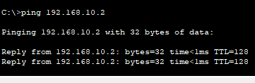
a. 从 PC1 ping PC6。
PC-1执行:
ping 192.168.10.2
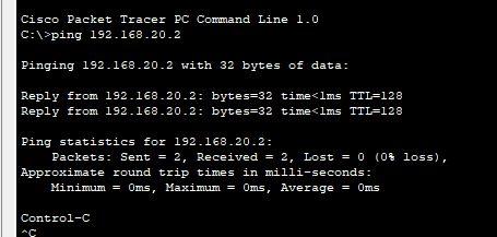
b. 从 PC2 ping PC5。
PC-2执行
ping 192.168.20.2
c. 从 PC3 ping PC4。
PC-3执行
ping 192.168.30.2
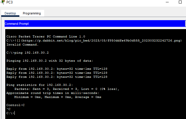
都是通的。
0x70 文件下载
2小时23分
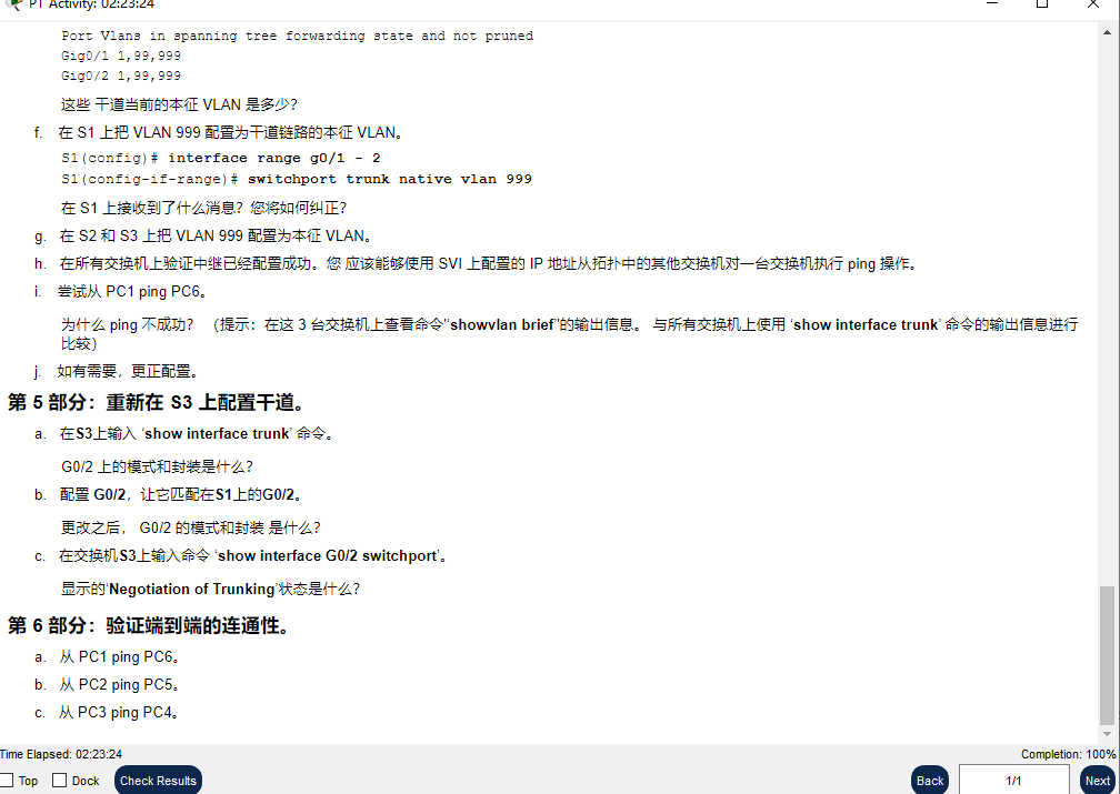
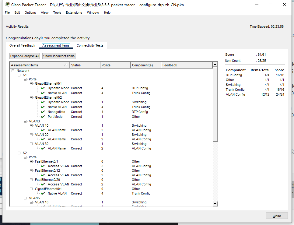
链接:
https://p.dabbit.net/blog/pic_bed/2023/03/35d4f8994ee3fd13_202303232244150.zip